
What is the answer to the JEE Advanced 2021 dipole–loop work question?
Option C is correct: work varies as the square of dipole moment and the inverse sixth power of separation. This JEE Advanced 2021 electromagnetic induction question is from Paper 2, Physics, under Electromagnetic Induction and Alternating Currents. It is single-correct; medium is the question bank’s classification, not an official exam rating, and the bank’s expected solving time is 120 seconds.
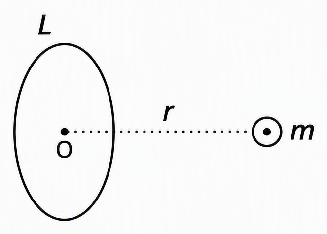
A magnetic dipole is brought quasistatically from infinity to a specified distance from a loop’s centre, using the process referenced in the original question. Find how the required work depends on dipole moment and final separation. The supplied question refers to an earlier setup that is not included, so we follow the supplied official solution without reconstructing its orientation, dimensions or circuit details.
The supplied choices use these symbols:
- A
- B
- C
- D
Follow the derivation below, especially the flux-to-current step. That is where the model’s assumptions enter.
How does the dipole field determine the external flux?
The official treatment makes external flux proportional to the dipole field, with the loop and geometric factors held fixed. We track dependence on dipole moment and separation; during any one approach, the moment stays constant while separation changes. The supplied starting relation is:
The missing setup does not justify selecting an exact axial or equatorial field formula. With fixed factors absorbed into the proportionality constant:
Introduce a bookkeeping constant:
The constant collects factors independent of moment and separation within this treatment. This scaling applies to the referenced process; it is not an exact flux formula for every finite loop and dipole arrangement.
How does changing flux produce the accumulated current?
The current follows from integrating the inductive equation, not from equating current with instantaneous emf. The official method uses an ideal energy-storage model, with fixed self-inductance and self-flux linkage defined by:
Within this model:
Take the induced current as zero at the infinity reference, before the external flux changes. Integrating from that reference gives:
The dipole’s external flux tends to zero at infinity, so:
The minus sign expresses opposition to the flux change. It does not affect energy, which contains current squared.
Emf depends on the rate of flux change; this current depends on the accumulated flux change. For the same endpoints, a slower approach gives a smaller instantaneous emf but the same final current in this model. This is not a universal current–flux law for resistive loops, nor a claim that the omitted setup explicitly states particular circuit properties.
Why does work have an inverse sixth-power dependence on distance?
The supplied process identifies quasistatic work with magnetic energy stored in the loop’s induced current. Energy is quadratic in current, so both powers in the current expression double. This equality belongs to the official energy-storage model, not to a circuit that dissipates energy.
Substituting the current expression gives:
Holding the bookkeeping constant and self-inductance fixed gives:
The complete official chain is:
The inverse power of separation doubles because energy is quadratic in current. No extra dipole-field factor has been introduced.
How does confusing force with work produce option D?
Option D can arise from differentiating the correct energy and reporting the resulting force scale as work. A spatial derivative introduces one extra inverse power of separation, but also changes the physical quantity.
Write the already-derived energy using a positive constant:
Its spatial derivative has magnitude:
This produces option D’s dependence:
An energy gradient has units of force. The mistake is calculating that gradient and labelling it work; the question asks for accumulated work, already given by the energy change.
Use this derivative only to diagnose the wrong option after completing the official solution. It is not a replacement force-integration method.
How do I apply this method to three related induction questions?
Identify what stays fixed, then take ratios using the flux–current–energy chain. These are original practice questions from the same chapter, not additional verified JEE PYQs. Current symbols in the ratios below denote magnitudes.
What happens if the dipole moment doubles at fixed separation?
The current magnitude doubles and stored energy becomes four times its original value. In the same model, with the loop and separation fixed, current is linear in moment and energy is quadratic.
What happens if the final separation doubles?
The current magnitude becomes one-eighth and required work becomes one-sixty-fourth of their original values. Both comparisons use the same model for approaches from infinity, with the dipole moment and loop fixed.
What if two loops receive equal flux changes but one has twice the inductance?
The second ideal loop has half the current magnitude and half the stored energy. Equal imposed external-flux changes are an explicit condition, not something guaranteed by changing a physical loop’s dimensions.
Therefore:
Check this with the following original practice values:
Doubling inductance does not double energy here because current also changes. Before substituting into the energy formula, write down whether current or imposed flux change is being held fixed.
Next step: the past-paper archive on JEEnius and search every JEE Main paper from 2002 and every Advanced paper from 2007, by year, subject or chapter, each with a worked solution (free).
Related on JEEnius: Chemical Kinetics JEE 2025: Pseudo-First-Order Rate Error.
Frequently asked questions
What is the answer to the JEE Advanced 2021 dipole–loop work question?
Option C is correct: the required work is proportional to m²/r⁶, where m is the dipole moment and r is the final separation. In the supplied official treatment, induced current scales as m/r³ and work equals the stored magnetic energy, LI²/2.
Why is the work proportional to 1/r⁶ rather than 1/r³?
With the loop and geometric factors fixed in the official model, external flux and induced current both scale as 1/r³. Stored magnetic energy is quadratic in current, so the inverse power doubles to give work proportional to 1/r⁶.
Why does a slower approach give the same final induced current?
In the ideal energy-storage model used by the solution, integrating L dI/dt = −dΦext/dt gives LI = −ΔΦext for zero initial current. A slower approach reduces instantaneous emf but leaves the accumulated flux change unchanged for the same endpoints. This result is not a universal current–flux law for resistive loops.
Why is Option D, m²/r⁷, wrong in the dipole–loop question?
Differentiating the derived energy, which scales as m²/r⁶, with respect to separation produces a magnitude proportional to m²/r⁷. That energy gradient has units of force, not work. The question asks for accumulated work, so Option C remains correct.