
What is the best order to study Alternating Current for JEE?
Study Alternating Current for JEE with current as the reference phasor: series-circuit voltages then combine as vectors. Repair prerequisites, learn single elements, then build series circuits. Use the seven steps below to organise your study and repeat the source-to-power routine in questions.
- Repair only the prerequisites you need. Revise Ohm’s law, electrical power, sinusoidal phase and basic differentiation. These relations recover lead–lag rules instead of leaving them as mnemonics:
Differentiating a sine gives a cosine. That quarter-cycle shift explains capacitor current leading voltage and inductor current lagging voltage.
- Reconstruct a three-row R/L/C table from memory. Give it columns for resistance or reactance, current–voltage phase and average power. Include these entries:
- Resistor: current and voltage are in phase.
- Ideal inductor: current lags voltage by a quarter-cycle.
- Ideal capacitor: current leads voltage by a quarter-cycle.
- Read the source before calculating. Identify angular frequency and label peak and RMS values separately. The following peak-to-RMS conversions apply only to sinusoidal waveforms:
- Identify topology, then calculate reactances. Use the inductor and capacitor relations above, converting inductance to henries and capacitance to farads before substitution. This routine covers sinusoidal steady-state series circuits, not every network containing a resistor, inductor and capacitor.
- Take current as the reference phasor. Resistor voltage lies along it, inductor voltage is a quarter-cycle ahead, and capacitor voltage is a quarter-cycle behind. Subtract the opposing reactive components before combining them with resistor voltage.
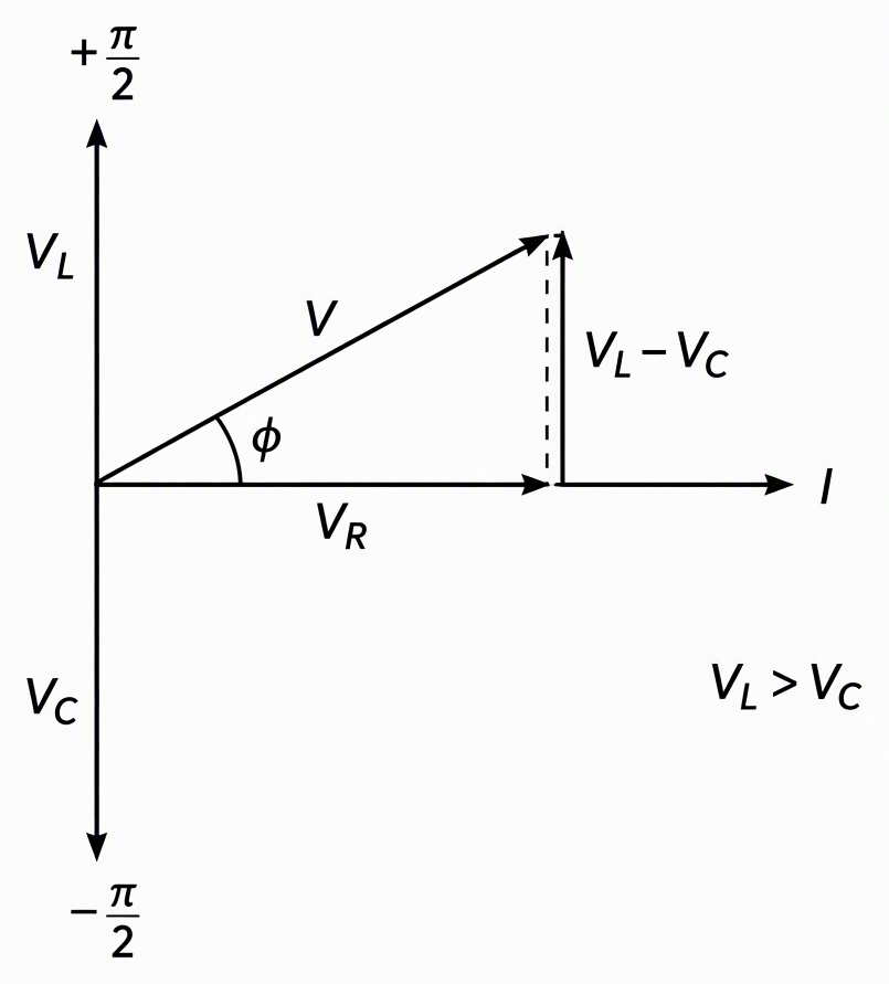
Define phase as voltage phase minus current phase. For nonzero resistance:
Positive phase means current lags; negative phase means current leads. Predict the sign from the larger reactance before calculating the angle.
- Calculate the requested quantity, then check power. Ideal inductors and capacitors consume zero average power. Their voltage magnitudes must not simply be added to resistor voltage.
- Study frequency changes and resonance after phasors. Inductive reactance rises with frequency; capacitive reactance falls. At resonance, a series RLC circuit has minimum impedance and maximum current for fixed source RMS voltage and fixed resistance.
Put the notes away and reconstruct the three-row table and phasor triangle. Keep transformers on a separate, subsequent practice checklist.
How do I find capacitor current without memorising the phase?
Differentiate the voltage first; convert to RMS afterwards. Differentiation sets the current waveform and phase; RMS conversion sets its effective magnitude. This and the next two examples are constructed teaching problems, not attributed JEE previous-year questions.
Problem: An ideal capacitor is connected to the following voltage. Find its current waveform, RMS current and average power.
Read the source:
The number 1000 is angular frequency, not frequency in hertz. Use the capacitor relation:
The positive quarter-cycle shift shows that current leads voltage. Independently check the amplitude through reactance:
Despite nonzero RMS current, average power is zero:
Instantaneous power is not always zero. Energy enters the capacitor during part of the cycle and returns during another part.
Diagnostic error: using peak voltage with RMS current mixes two conventions. Mark each supplied and calculated value as peak or RMS before multiplying.
How do I solve a series RLC circuit and check the answer twice?
Find the net reactance, predict the phase, then calculate current. Check average power by both the resistor and source formulas, then check the source voltage through the phasor triangle. These checks test different errors: peak/RMS consistency and voltage addition.
Constructed teaching problem: Find current, phase, average power and all three component RMS voltages for this series circuit:
Calculate the reactances:
Inductive reactance is larger, so current must lag. Make that prediction before calculating the angle.
Current therefore lags voltage by 45 degrees. The two power routes agree:
The same current flows through every series element. Multiply its RMS value by the resistance or relevant reactance to get each component RMS voltage:
Check the source using the phasor triangle, not the sum of voltage magnitudes:
Two tempting approaches fail here:
- Adding resistance and both reactances as positive scalars: the reactive voltages oppose each other and are perpendicular to resistor voltage.
- Assuming every component voltage must be smaller than the supply: the inductor voltage exceeds it here. The source equals the phasor sum, not the sum of magnitudes.
Why can the voltage across a component exceed the supply at resonance?
Large inductor and capacitor voltages cancel because their phasors point in opposite directions. Resonance means zero net reactance, not zero impedance or zero reactive component voltage. The resistor still limits current, so large individual reactive voltages do not violate the voltage law.
Constructed teaching problem: For this series RLC circuit, find resonant frequency, current and the inductor and capacitor RMS voltages:
Assume ideal inductance and capacitance, sinusoidal steady state and fixed source RMS voltage. First calculate angular frequency, then convert it to hertz:
At this frequency, the reactances are equal. Impedance is purely resistive, so the power factor is unity:
Calculate the component voltages rather than assuming they vanish:
Each is ten times the source voltage. Their opposite phasors cancel, leaving only the resistor voltage:
The nonzero resistance keeps current finite. Cancellation removes the reactive contribution to source voltage, not the voltage across either reactive element.
Below resonance, capacitive reactance is larger and current leads; above resonance, inductive reactance is larger and current lags. Explain those changes from the frequency dependence of reactance, without further arithmetic.
What should I practise next to become reliable at AC questions?
Choose your next set by your error, not the pages you finish. Use this practice ladder:
- Start with waveforms: source reading, peak-to-RMS conversion and single resistor, inductor and capacitor questions.
- Build series circuits: practise RL, then RC, then RLC, predicting lead or lag before calculation.
- Vary the conditions: practise resonance, frequency changes, power factor and voltage magnification.
Class 11 learners should repair prerequisites first; Class 12 students should follow the ladder. Droppers should start at the gap identified by these examples:
- Cannot reproduce example 1: return to differentiation, phase and RMS.
- Solve example 1 but fail example 2: practise phasor construction.
- Complete the arithmetic but cannot explain example 3: work on resonance and cancellation.
Keep ideal transformers in a separate block. Use turns ratios and power conservation, not series impedance; the currents below are RMS values:
For JEE Main, practise single-correct and numerical-answer questions. For Advanced, progress to problems combining waveform, phase, power and changing parameters.
Tag every wrong answer with one primary error: peak/RMS, frequency/angular frequency, phase sign, topology, units, phasor addition or power. Redo it from a blank page before reopening the solution.
Readiness means reconstructing the triangle, explaining phase before calculation and verifying current or power by a second route. For your next topic-specific drill, JEEnius daily practice problems provide a fresh ten-question set every day, with free sets daily; choose the topic exposed by your diagnostic.
Next step: daily practice problems on JEEnius and get a fresh ten-question set on a topic every day (free sets daily).
For a worked example of the same idea, see Atomic Structure Practice Questions JEE: 5 Solved Drills.
Frequently asked questions
In what order should I study Alternating Current for JEE?
Revise Ohm’s law, electrical power, sinusoidal phase and basic differentiation first. Study individual resistors, inductors and capacitors, then source reading and RMS conversion, followed by series RL, RC and RLC circuits using phasors. Finish with power, frequency changes and resonance, keeping ideal transformers in a separate practice block.
How do I know whether current leads or lags in an RLC circuit?
For a sinusoidal steady-state series RLC circuit, compare inductive reactance with capacitive reactance. Current lags the source voltage when inductive reactance is larger and leads when capacitive reactance is larger. At resonance, the reactances are equal and current is in phase with the source voltage for nonzero resistance.
Why can capacitor voltage exceed supply voltage at resonance?
In a series RLC circuit at resonance, the inductor and capacitor voltages have equal magnitudes but opposite phasors. They cancel in the source-voltage sum even when each exceeds the supply voltage. Nonzero resistance limits the current, and the resistor voltage equals the source voltage.
How can I avoid mistakes in JEE Alternating Current questions?
Label peak and RMS values separately, distinguish angular frequency from frequency, and convert component values to SI units before substitution. Predict lead or lag before calculating, and combine series-circuit voltages as phasors rather than adding their magnitudes. Check average power using both the source and resistor formulas, then tag each wrong answer with its primary error and redo it from a blank page.